Part I
A few months ago at band practice Bill mentioned ring modulators, and asked if I knew how to make one. I had seem some circuits and knew they were pretty easy to construct so I said yeah, no problem, give me some time. Since my life is basically just going from project to project, I had some other stuff to clear out before I could get to this one. I wrapped up some other stuff and started fleshing out the project after Christmas.
A ring modulator is a device that multiplies two audio signals together. Usually you have a carrier frequency, a sine wave or something like that, and another audio signal like a guitar or piano or something. Bill sent me a really sick example of the Mahavishnu Orchestra playing live, with one hell of a ring modulated Rhodes solo somewhere in it. Most modern ring modulators are actually balanced modulators, but the effect is basically the same. The ring in ring modulator comes from the shape of the diode configuration.
after a little research settled on this design which consists of a couple audio transformers, four diodes, and a signal generator.
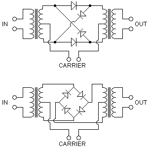
With the exception of the signal generator, the circuit is passive, and if you use an incoming carrier signal instead of a generated sine or square wave, it requires absolutely no power. I could have used the much more complicated “modern” circuit, but decided to stick to the analog approach. Here is the parts list:
- 2 x TM018 Audio Transformers
- 4 x 1N4002 Diodes (I used matched pair germanium diodes instead).
- 3 x Mono Audio Jacks
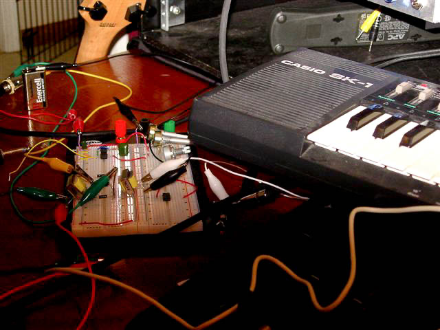
I assembled the circuit on breadboard, using an atari punk console as my signal generator (since it happened to be sitting on the breadboard already), and ran a few tests. To be honest it sounded like shit. At first I was testing with a guitar and just couldn’t get a good sound out of it, it was scratchy at best, and the apc was overpowering the guitar. I figured the output level on the guitar must be too low, then after a few minutes the atari punk console (signal generator) gave out, so I walked away for a while out of frustration.
A day or so later I came back to it with a new strategy. Rather than test with a guitar and the APC, I could just test with two synthesizers, one generating some simple carrier tones, and the other controlling the melody. The XP-50 was already hooked up, and the Casio SK-1 had some batteries in it, so what the hell, I gave it a shot. This was working much better, and after some tweaking I was starting to get some quality sound out of it.
Not too bad, sounds like a ring modulated keyboard. Surely a more talented ivory-tickler could do better. I thought about it for a few minutes and realized that the signal levels of the carrier and source signal would have to be at the same level (not volume) for the output to sound correct. This mismatch in level is why the guitar APC combo didn’t work, but this did, since the keyboards were both at line level. When I build the final circuit I’ll have to remember that. There is also some leakage in the carrier (nobody wants to hear the modulating frequency) which I’ll have to address, its probably due to the voltage drop across the diodes (1.6 volts?), but that should be no big deal. I might also throw an opamp on the output to drag the signal level back up.
Part II
The circuit I started with would have needed a preamp for my input signal and a separate oscillator. In addition, I would have probably needed some means of amplifying the output signal, and mixing the effected and un-effected signals together. I’m not quite good enough with circuits to throw all of those disparate components together on the fly, so I sought out another circuit that had this integrated into the design.
I came across this design based on the AD633 chip and a reference to a design by Roman Sowa:
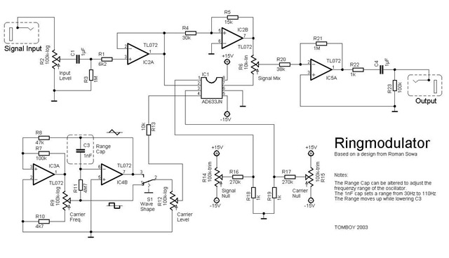
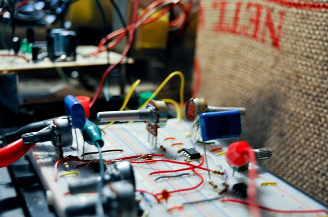
I actually found several different circuits based on Roman Sowa’s design, but I liked this one. It was clear and concise, easy to read, and split the components up into easy to understand modules. You can clearly see the input stage, the oscillator (with waveform selector…another bonus), the multiplier and the output stage. I got to work in the basement prototyping this design to see how it sounded.
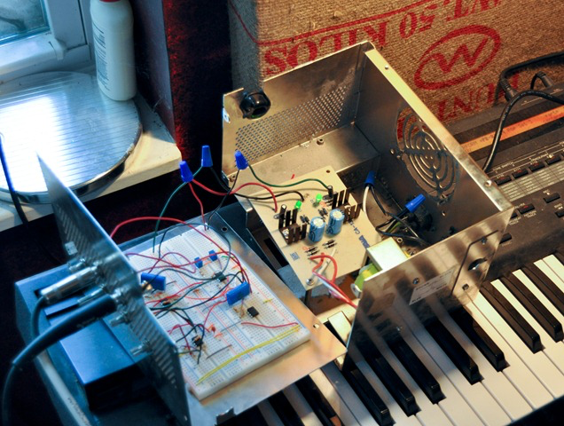
Most of the components I used were whatever I had on hand, with the exception of the very expensive AD633 chips (8 bucks from digikey). The pots I used were whatever linear equivalent pots I had laying around. I figured that would work for the prototype testing, if I liked how everything was turning out I could pick up the real pots as part of a second order, and design the PCB while I waited for them. The power supply is an old kit I built up about a decade ago from Craig Anderton’s book…still delivers 18 V as steadily as the day I built it. You’ll note the schematic calls for 15 V, but the TL072 and AD633 chips this circuit is based on can easily handle 18 V, so I just used what I had.
Since I had an input stage to work with this time, I tested with a guitar. Very little carrier leakage (to be resolved with tweaking the null pots), steady oscillation without the need of a separate carrier instrument, everything integrated into one circuit
Part III
If I had enough time to do it right it’d take me less than a week, it’d be stable, and I wouldn’t be worried that a 3 foot tumble would render it useless. But alas, Bill had some gigs coming up, and I wanted to put this project to rest in the interest of getting some of my time back, so I resorted to some rather ridiculous means to complete it. What follows is not to be emulated or admired, merely witnessed.
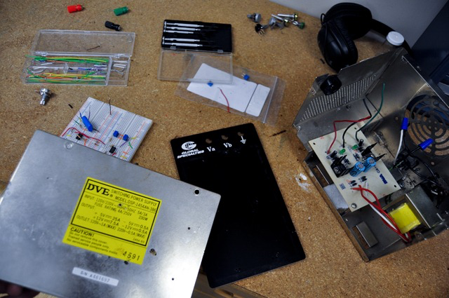
I had assembled the circuit on a breadboard in the previous part, I had a working prototype that if you pinched the alligator clips just right, would produce the effect I was looking for. I had a day or so to get this thing boxed up and stable enough to work at some gigs, not nearly enough to design the PCB, etch, reassemble, test and ship. What’s a time-starved designer to do? Box up the prototype breadboard and all, right into the oversized power supply box, wiring up the controls right to the front panel.
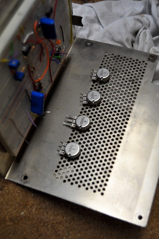
I started the process by first removing the breadboard strips from the substrate they were attached to.
The entire breadboard wouldn’t fit assembled into the case so I simply transferred the screw hole locations from the substrate to the new case so I could attach the strips to the inside. After drilling and attaching the strips it looked something like this:
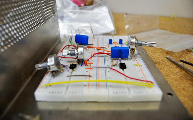
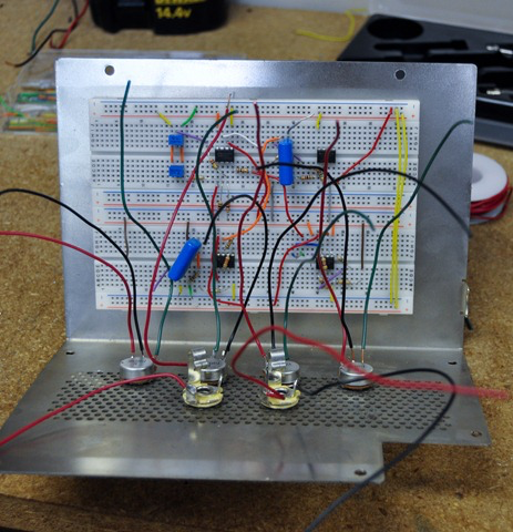
Moving the controls from the board to the panel was easy enough. As you can see I had to settle for using the PCB mount pots I ordered expecting to mount this on a board, rather than the panel mount ones which are much easier to solder wire to. Live and learn I guess. I drilled holes for the 4 controls knobs (Frequency, Depth, Pre and Post Gain) in a row on the panel, along with two more for the input and output. I tried to keep everything on one detachable panel so that if I ever did get around to designing and etching a board I could replace the breadboard strips with it and not have to make any other modifications, I did, after all, order two of everything.
With the wiring soldered to the pots I jammed the other ends of jumper wire where the pots used to reside on the board and ran a final test. Everything appeared to be working, so I wired up the power directly to the terminal strips and packaged it all together.
There, done. For now.